 |
Create a piece of jewellery using ReliefVTR.
Adjust program.
Should there still be data from the last task in the program then save these using Save . Data or Save under. Thereafter delete all data memory using New . File. |
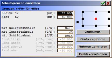
Adjust your work area in Layout . limits with a dimension of X=32mm x Y=45mm, centre in the X middle (comp. image).
 |
Input graphic.
Change into the menu draw, and input the 2D paths for the relief object.
Input cross.
The cross is created by 2 cylinders blended using OR. For this input a vertical line with the end points [PosnA, X=0, Y=2.5mm], [PosnE, X=0, Y=42.5mm] and a horizontal line with end points [PosnA, X= -13.5mm, Y=27.5mm], [PosnE, X=13.5mm, Y=27.5mm].
Mark both lines, change into ReliefVTR and generate an empty relief using New relief. You can retain the proposed resolution for a first test. |
 |
In ReliefVTR the marked adopted graphic is displayed in the colour greenish blue.
Here select the function Cylinder. following the request Select first track select the two line. |
| Progression:

|
Select Progression . Select section . Radius + and specify the exact radius progression (inputs comp. image, height = 3.5mm).
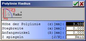
Save the polyline, e.g. under the name CrossRadius in the directory PROJECT.
Note: Although a similar progression can also be generated using section selection, this, however, does not correspond to an exact radius. |
| Ends:

|
Select Ends cropped. |
| Sides:

|
Select Sides = double-sided. |
| Base height:

|
Leave the Base height at 0. |
| Logic:

|
Select the logic OR (max). |
| generate:

|
Using generate calculate the graphic. |
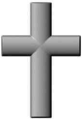 |
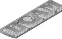
Relief from the two cropped lines. |
Input ellipses into the middle of the cross.
| 1 |
Select the menu draw |
| 2 |
Select EllipseMP Rx,Ry. |
| 3 |
Input the centre with X=0 and Y=27.5mm. |
| 4 |
Input the extension with radius X=3.3mm, radius Y=4.65mm. |
| 5 |
Mark the input ellipse, and change into the function operate . displace contour. |
| 6 |
Here, using Offset=0.5mm, correction inwards, round-off around and preserve original, calculate a second inwards displaced ellipse. |
| 7 |
Mark the first ellipse again and, using displace contour and offset=1.7mm, calculate a further ellipse (all other inputs remain unchanged). |
| 8 |
Mark the 3 ellipses and change into ReliefVTR. |
 |
Select Border + Plan, mark the outer ellipse and specify the parameters Surface height = 3.5mm, Border progression OFF and Logic = OR (comp. image). |
 |
Select Border + Plan, mark the outer ellipse and specify the parameters Progression: Radius = 0.5mm, Surface height = 0, Border progression ON and Logic = ADD (comp. image). For the surface relief progression this time select the standard polyline input: End height of the polyline = 0.5mm, Start value = 0, Width of the polyline = 05mm, Start angle = 0, End angle = 90°.
The program automatically generates a name and saves the polyline in the PROJECT directory. |
 |
Select Border + Plan, mark the inner ellipse and specify the parameters Surface height = 0.5mm, Border progression OFF and Logic = Sub (comp. image). |
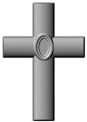 |
The relief generated up to this point. |
 |
Select the menu draw.
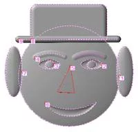
Draw the curves on the previous relief. For this you can display the relief as background image. Now construe the lines (comp. graphic).
Mark the lines and change into ReliefVTR. |
 |
Here, select the function Cylinder and select all lines using a rectangle. Input the parameter using Progression 0.2mm x 0.15mm, ends rounded off, base height = 0, Logic = SUB. |
 |
The relief generated up to this point. |
 |
Raise the cross with surroundings.
A contour around the relief surface can be determined. For this select Edit relief . layer border . ABSOLUTE. Here select a Z point somewhat bigger than 0. After confirmation using open a window for the positioning of the border search. Displace the level so far downwards until the cross is just black enough to raise it from the background. The setting Concentrate is set to the smallest value. After the start you obtain a border around the cross.
Select Back in the CAD. The contour is adopted marked.
Select the function operate . displace contour. Here, calculate an outwards displaced contour Offset=1.0mm, correction outwards, rounding off pointed and delete original .
Select edit . round off corners, input a corner radius of 6.0mm und click-on the 4 internal corners one after the other following parameter input. These corners are now rounded off.
Mark the contour and change to ReliefVTR. |
 |
Select Border + Plan, mark the contour and specify the parameters Surface height = 0.7mm, Border run off and logic = ADD (comp. image). |
 |
The relief generated up to this point. |
 |
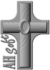
Input AHSoft signature.
Change to back in the CAD.
Import the AHSoft signature.
Edit the signature as shown in the graphic.
Mark the signature and change to ReliefVTR. |
 |
Select Border + Plan, mark the contour and specify the parameters Surface height = 0.6mm, Border progressionOFF and logic = ADD (comp. image). |
 |
 |
|
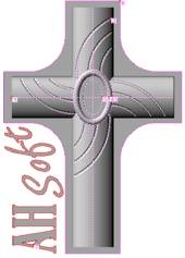
| Relief graphic with object lines. |
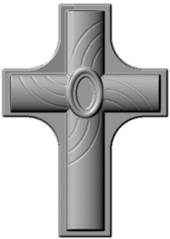
At the end the object should appear as shown in the image. |
The finished relief. |
Calculate milling data.
If the graphic is in order then calculate the relief again using the desired milling resolution. For further courses of action please observe the Relief work specification . Calculate milling data.
Finished! |