Milling data from relief.
Milling data can be created in the Relief program from data of different origins. The relief can be imported or opened in various formats, designed in ReliefVTR or the relief data can be a combination of imported data and relief design. Here the creation of milling data from an imported STL is described.
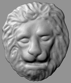
Import shape.
  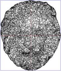
Import the STL data (here Lion.STL). For import, the STL surfaces are displayed as graticule. The surfaces can, as required, be rotated in 3 axes. In this case all angles remain at 0 (the shape finds itself in the correct position for milling). Confirm the angle input. The program shows the determined relief position and extension. Also confirm the display. The data are imported into the relief
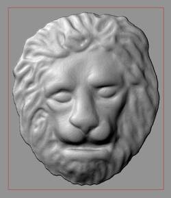
Prepare relief.
The complete shape is to be milled. For this the tool must be able to reach all points in the relief. In order to guarantee this, a wide border is necessary around the head. For this the relief is enlarged using Relief file . Modify frame . Limits . Add border. For input see Graphic.
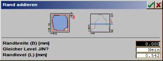
Input add border:
| Border width (B) [mm]: |
1.000 |
| Same level Y/N?: |
No |
| Border level (l) [mm]: |
Remains unaltered |
Calculate milling data.
For the milling path calculation on relief select the functions in Relief AutoCorr. An automatic milling path calculation for several tools can be found in Relief AutoCorr . Relief AutoCorr.
For the milling path calculation a premilling and finishing tool are employed.
| Tools used: |
Premilling tool:
end mill cutter |
Finishing tool:
Relief cutter with cone |
| Snr Scheiden-/Schaft radius: |
3.000 |
3.000 |
| CuT Cutter tip: |
1.000 |
0.000 |
| CAn Angle: |
0.000 |
20.000 |
| Frk Cone radius: |
0.000 |
0.200 |
| FEt Eintauchtiefe: |
0.000 |
0.000 |
| Off Safety height: |
1.000 |
1.000 |
| VXY Working feed XY: |
1.000 |
0.600 |
| IFZ Incision feed Z: |
0.800 |
0.500 |
| Spd Spindle rpm: |
30000 |
40000 |
| Tlt Tool life travel: |
unused = 0 |
unused = 0 |
| CSt : Changing station |
1 |
2 |
| Settings Relief AutoCorr. |
Premilling tool: |
Finishing tool: |
| Tool # |
1 |
2 |
| Clearance process: |
Right, spiral |
Clearance angle (0°) |
| Clearance direction [I/O]: |
outwards > inwards |
Outwards > inwards |
| Clearance track separation [%]: |
50 |
20 |
| Layer separation Z (1st track) %: |
100 |
OFF = 0 |
| No. of clearance layers (1..99): |
1 |
1 |
The setting of the parameters remains unchanged.
Check and export milling data.
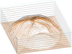
Check the calculated milling paths using Norm + Zoom projection.
 |
The milling paths can be exported without diversion using PLayer Export in the format of the milling machine. For this it is branched into Export selection. Here, select for example DIN/ISO for the export to a professional milling machine with DIN/ISO control. |
|