



What Is a TS11 Pneumatic Breaker and How Does It Work?
A TS11 Pneumatic Breaker is a compact impact tool designed to fracture hard materials with repeated piston strikes. It commonly appears in construction, repair, quarrying, and maintenance work. Its power comes from compressed air, not an electric motor or fuel engine. That difference matters in dusty or demanding work areas.
The operating cycle is direct. Compressed air enters the breaker through its inlet. Internal valves guide the air above and below a piston. The piston moves rapidly and transfers force to the working tool. The tool then strikes rock, concrete, masonry, or another approved surface. Exhaust air leaves through the outlet, and the cycle repeats many times each second. It sounds simple. It is not entirely simple.
Performance depends on air pressure, hose size, lubrication, tool condition, and operator technique. A restricted hose can weaken each blow. Poor lubrication can increase wear around moving parts. A loose connection may waste air and create unnecessary noise. Experienced users inspect these details before demanding full impact power. They also confirm the manufacturer’s specifications, because TS11 configurations may differ between suppliers or production periods.
This guide explains the TS11 Pneumatic Breaker through its main components, working sequence, practical applications, and maintenance needs. It also considers limitations that product descriptions sometimes overlook. No tool works perfectly in every material. The breaker may feel powerful, yet incorrect pressure or a damaged bit can reduce results quickly. Reliable operation requires training, protective equipment, controlled handling, and regular inspection. Safety should remain part of the mechanism, not an afterthought.
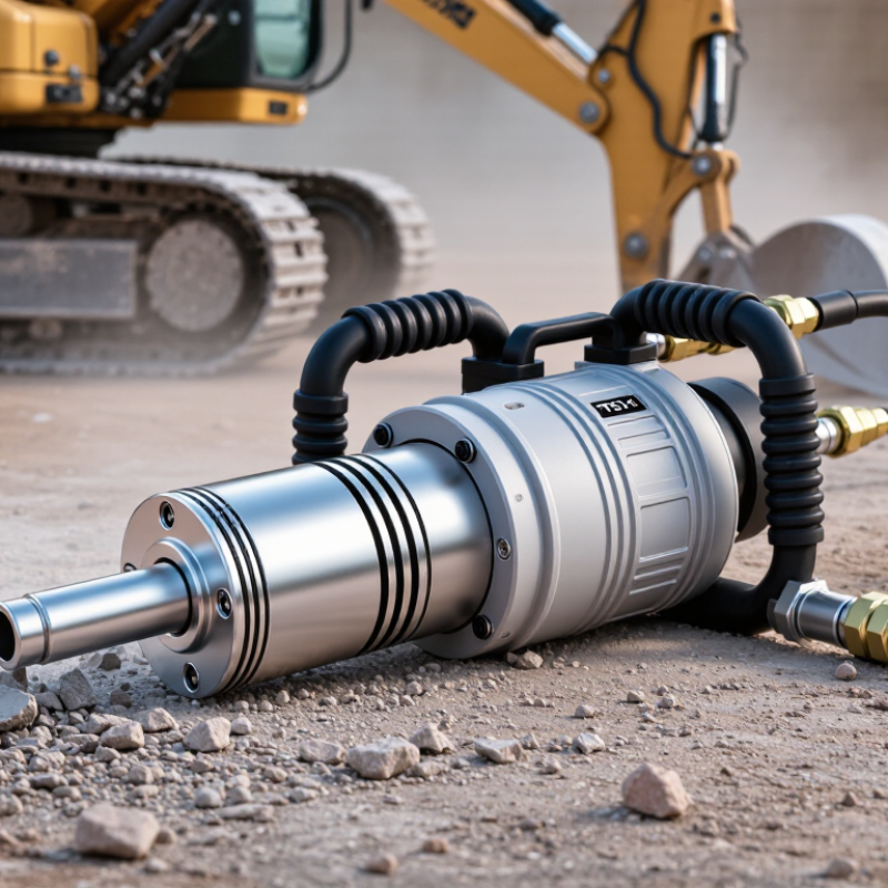
TS11 Pneumatic Breaker: Definition, Design, and Core Components
What Is a TS11 Pneumatic Breaker and How Does It Work?
A TS11 pneumatic breaker is a compact impact tool powered by compressed air. Its designation can vary between suppliers, so technical drawings should confirm the exact specification. The main assembly includes a steel housing, air inlet, control valve, cylinder, piston, tool retainer, and exhaust passages. Inside the cylinder, compressed air moves the piston back and forth. The piston strikes a working tool, such as a chisel or moil point. That repeated impact breaks concrete, masonry, or compacted material. It is simple, but not effortless.
Its design depends on balanced airflow and precise sealing. The valve directs air above and below the piston. The retainer keeps the tool aligned during impact. Lubrication reduces friction, while exhaust ports release used air and heat. The U.S. Department of Energy reports that compressed air can consume 10% to 15% of industrial electricity, and sometimes more. Therefore, leaks and low-pressure operation can increase running costs. Noise and vibration also require attention. The design is effective, yet operator comfort may be underestimated.
Tips: Check hose diameter, air pressure, and coupler condition before use. Drain moisture from the airline. Apply the specified pneumatic oil. Inspect the retainer and tool shank frequently. A worn seal may cause weak impacts and excessive air use. The U.S. National Institute for Occupational Safety and Health recommends controlling noise and vibration exposure, not merely wearing protection. Field testing should guide maintenance intervals, because dusty sites rarely behave like laboratory conditions.

Air-Powered Operation at Typical 90–100 psi Working Pressure
What Is a TS11 Pneumatic Breaker and How Does It Work?
Air-Powered Operation at Typical 90–100 psi Working Pressure
A TS11 pneumatic breaker converts compressed air into repeated impact energy. At roughly 90–100 psi, air enters the internal valve chamber. The valve alternately drives a piston forward and backward. That piston strikes the working tool, producing rapid blows against concrete, masonry, or compacted material. The exhaust air then leaves through the housing, keeping the cycle moving. It sounds simple. It is not always simple in the field.
Pressure alone does not determine performance. The compressor must also supply enough airflow, usually stated in cubic feet per minute by the equipment specification. The U.S. Department of Energy reports that compressed-air leaks can waste 20–30% of compressor output in industrial systems. A damaged hose, restrictive coupling, or clogged filter can therefore reduce breaker force, even when the gauge still shows 100 psi. That detail is often overlooked.
Clean, dry air matters. ISO 8573-1 provides a recognized framework for controlling particles, water, and oil in compressed air. Moisture can accelerate internal wear and contaminate lubrication. Before operation, technicians should inspect connections, confirm the rated pressure, and use the recommended air-line oil. The exact oil volume may vary. Checking the service manual remains safer than relying on habit. In practice, operators sometimes blame the breaker when the real problem is inadequate airflow or poor air preparation.
What Is a TS11 Pneumatic Breaker and How Does It Work? - Air-Powered Operation at Typical 90–100 psi Working Pressure
| Data Dimension | Typical TS11 Pneumatic Breaker Data | Operating or Selection Notes |
|---|---|---|
| Tool Type | Handheld pneumatic breaker | Designed for repeated impact work such as breaking concrete, masonry, asphalt, and compacted material. |
| Power Source | Compressed air | An air compressor supplies pressurized air to reciprocate an internal piston and generate impact energy. |
| Typical Working Pressure | 90–100 psi (6.2–6.9 bar) | Use the pressure specified for the particular tool configuration. Excessive pressure can increase wear and reduce operating safety. |
| Operating Principle | Reciprocating piston impact | Compressed air alternately drives the piston forward and backward. The piston strikes the tool bit, transferring impact energy to the work surface. |
| Typical Impact Rate | Approximately 1,200–1,600 blows per minute | Actual impact rate depends on air pressure, air volume, hose size, tool-bit resistance, and internal condition. |
| Approximate Air Consumption | Approximately 35–55 cubic feet per minute (cfm) at rated pressure | The compressor should provide sufficient delivered air volume at the tool, not merely the compressor’s advertised maximum output. |
| Recommended Air Hose | Usually 3/4-inch inside diameter for demanding continuous operation | A larger hose and short, unrestricted air path help reduce pressure drop. Confirm the connection size before installation. |
| Air Connection | Commonly 3/4-inch nominal inlet on heavy-duty breakers | Fittings must be compatible with the tool inlet and rated for the working pressure. The exact connection can vary by configuration. |
| Tool Shank | Common heavy-duty hex shank; size must match the selected model and retainer | Use only bits with the correct shank profile and length. A loose or incorrect bit can cause poor performance and a safety hazard. |
| Lubrication | Pneumatic-tool oil supplied through the air inlet | Regular lubrication reduces friction, helps protect internal parts, and supports consistent piston movement. Follow the tool’s maintenance instructions. |
| Main Control | Hand-operated throttle or trigger valve | The control meters compressed air into the cylinder. Release the control before disconnecting the air hose or changing accessories. |
| Typical Applications | Concrete removal, asphalt repair, masonry work, trenching, and demolition | Select the bit shape and operating technique according to the material and job conditions. |
| Operator Position | Two-handed operation in an upright or controlled working posture | Maintain a firm grip, stable footing, and a balanced stance. Do not use the tool above shoulder height unless the equipment instructions specifically allow it. |
| Noise and Vibration | High noise and substantial hand-arm vibration are typical | Wear hearing protection, eye protection, safety footwear, gloves, and suitable respiratory protection when dust is generated. |
| Key Performance Factors | Air pressure, delivered air volume, hose diameter, lubrication, bit condition, and operator technique | Maintaining rated pressure alone is not enough; insufficient air volume or excessive hose restriction can noticeably reduce impact performance. |
| Basic Pre-Use Check | Inspect the hose, couplings, throttle, retainer, tool bit, and housing | Do not operate the breaker if parts are cracked, loose, excessively worn, or leaking air. |
How the Piston, Valve, and Tool Shank Generate Impact Energy
What Is a TS11 Pneumatic Breaker and How Does It Work?
A TS11 pneumatic breaker uses compressed air to create repeated impact energy. Air enters the cylinder and drives the piston through a controlled stroke. The valve then redirects airflow, sending the piston back for another cycle. This switching action happens rapidly, but its timing must remain stable. Even a small air leak can reduce impact strength and increase operating noise.
The piston transfers its force to the tool shank, which carries the blow into the working bit. The shank must sit squarely in the breaker’s front guide. Poor alignment can cause uneven wear, vibration, and chipped contact surfaces. In practical maintenance, technicians often inspect the shank before blaming the piston. That judgment is not always correct, but it prevents needless internal repairs. Clean air, suitable lubrication, and steady pressure help preserve the valve and piston surfaces. Excess oil can also create problems.
Tips: Check the shank for mushrooming, cracks, or unusual polishing before each shift. Keep the air hose free from sharp bends. Listen for a change in rhythm. A slower, irregular beat may indicate restricted airflow, worn seals, or valve contamination. Do not force a dull tool. It can make the breaker work harder while producing less useful impact.
Air Consumption, Blow Rate, and Industrial Performance Metrics
What Is a TS11 Pneumatic Breaker and How Does It Work?
A TS11 pneumatic breaker uses compressed air to drive a piston against a working tool. Air enters the cylinder, pushes the piston forward, then redirects to reset it. This repeated movement creates the breaker’s impact force. The tool does not produce steady torque. It delivers short, forceful blows for concrete, masonry, scale, and similar materials.
Air consumption and blow rate define much of its industrial performance. Air consumption shows how much compressor capacity the breaker needs during operation. A restricted hose can reduce pressure, even when the compressor appears powerful. Blow rate, measured in blows per minute, indicates working speed. However, a higher rate does not always mean faster production. Impact energy, operator control, material hardness, and tool condition also matter. Measure inlet pressure while the breaker is running, not only at rest. That distinction matters.
Tips: Use the recommended hose diameter and check for leaks before each shift. Record pressure, air use, blow rate, and output during a short test. Field results can differ from catalog figures. Moisture, worn seals, and poor lubrication may change performance noticeably. I would also avoid judging the breaker by sound alone; a loud tool is not automatically a productive tool. Vibration and fatigue deserve attention, although they are sometimes overlooked during routine checks.
Safety Standards, Lubrication, Maintenance, and Service Requirements
A TS11 pneumatic breaker converts compressed air into rapid piston impacts for breaking concrete, masonry, or compacted material. Safe operation begins with the air supply, not the trigger. Use a regulated line within the tool’s rated pressure, and inspect hoses, couplings, retainers, and the working bit before each shift. Damaged fittings can fail suddenly. Follow applicable occupational safety rules and the requirements for handheld pneumatic tools, including hearing, eye, foot, and respiratory protection when dust is present. Keep both hands stable and never point the breaker toward people.
Lubrication protects the piston, cylinder, and internal seals. Add approved pneumatic-tool oil through the air inlet according to the service instructions, then connect the hose and run the breaker briefly. Too little oil increases wear; too much may create oil mist at the exhaust. Drain moisture from the compressor and filter regularly. Water inside the tool is a quiet cause of corrosion. Disconnect the air supply before clearing a jam, changing bits, or opening any housing.
Maintenance should include checking fasteners, vibration, air leakage, trigger movement, and unusual impact sounds. Service frequency depends on duty cycle, dust, pressure, and daily operating hours. In practice, inspection is often skipped when production is urgent. That is a weak habit. A trained technician should replace worn seals and impact components, verify the regulator, and test the tool after assembly. Do not rely on appearance alone; a breaker can look clean while internal wear is already reducing control and safety.
Article Source:
Siemensstraße 13-15
47608 Geldern
NRW Deutschland
Mail: sale@atmmachinesolutions.com
Head office:
+49 (0) 2831 91021-20
Fax:
+49 (0) 2831 91021-99
SUPPORT and INFO
from 3 p.m. to 6 p.m:
+49 (0) 2831 91021-60
( please ring for a long time )
Monday to Friday
8.00 – 12.30
and 13.00 – 15.00
Visit / collection by appointment only!
➣ Sign up for our newsletter
Benefit from a 20% discount, don’t miss any events and always stay up to date.
To access the actual content, click on the button below. Please note that data will be passed on to third-party providers.
More information